Vision 2448 User Manual
Browse online or download User Manual for Engraver Vision 2448. Vision 2448 User manual
- Page / 44
- Table of contents
- BOOKMARKS
Summary of Contents
Page1Liability Statement ________________________________________ 2Safety ____________________________________________________ 3Chapter 1: Unpacking a
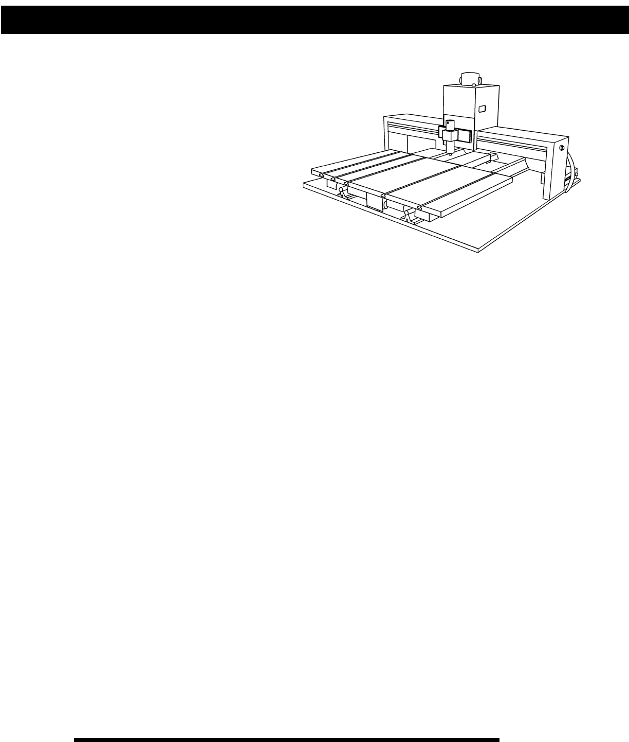
Page10Chapter 2(Figure 2.1) Series 3 full linear T-slot table format. Shown here is the top view ofthe Series 3 Vision 1624. The Vision 1212 and th
Page11Chapter 23. T-Slot Table. Also referred to as the work surface, this aluminum bed supported by thelinear rails allows placement of the engravin
Page121. Engraving Motor. The engraving motor or “spindle motor”, is the large black motor onthe top of the carriage assembly. The engraving motor d
Page13Chapter 2(Figure 2.3) Series 3 flatbed (moveable gantry) table format. Shown here is a topview of the Series 3 Vision 2424.1. Table Base Plate2.
Page14Chapter 23. X-Axis Lead Screw. This is a threaded rod located underneath the table base.Combined with the stepper motor, the lead screw is rota
Page15Connection of Power, Cables, and ControllersAdditional boxes may have been shipped along with your table, depending on the systemordered. These
Page16Chapter 3
Page17Spindle Assembly DescriptionOur most recent tables (the “Series 3’s”) include our newest spindle design, which nowincorporates tension spring ad
Page18Chapter 4Zeroing Cutters for Top-Loaded Spindles (see figure 4.1)1. Turn the micrometer to zero. This provides a starting point and reference fo
Page19Chapter 4Diamond EngravingTo install a diamond drag adapter, remove the retainer ring and nose cone from the bottom ofthe spindle and replace wi
Page2Copyright 1998 Vision Computerized Engraving & Routing SystemsCopyright 1998 Vision Computerized Engraving & Routing SystemsCopyright 199
Page20Chapter 4(Figure 4.4) Series 3 SpindleShown With Diamond DragAdapterPulleySpindle HousingMicrometerDiamond DragAdapterPressure SpringAdjuster
Page21Chapter 5:Chapter 5:Chapter 5:Chapter 5:Chapter 5:TTTTTable Maintable Maintable Maintable Maintable MaintenanceenanceenanceenanceenanceChapter 5
Page22Chapter 5CarbonMotor Brush(Figure 5.2) The engraving motorand brushesShown from front and side viewCleaning the Vacuum Filter (only with the vac
Page23LUBRICATIONLubricating the X-Axis, Y-Axis and Z-Axis lead screws(ALL MODELS)A light lubrication of the X and Y and Z lead screws shouldbe perfor
Page24Chapter 5(Figure 5.4)Spindle Lubrication (for Series 3 Vision Tables only)The spindle assembly in the Series 3 Vision Tables requires amonthly l
Page25Chapter 6:Chapter 6:Chapter 6:Chapter 6:Chapter 6:Earlier TEarlier TEarlier TEarlier TEarlier Table Modelsable Modelsable Modelsable Modelsable
Page26Chapter 6Chapter 6Chapter 6(Figure 6.3) Series2 flatbed (moveable gantry) table with THK carriage design.Shown here is a top view of the Vision
Page27Motor SpeedController PlugStepper MotorsCarriage AssemblyEngraving MotorY-AxisLead ScrewBase PlateQuick Lock ViseT-Slot TableMaterialGuides(Figu
Page28Chapter 6MAINTENANCE FOR EARLIER MODELSMost maintenance procedures are similar to those for the current models. However, theprocess for lubrica
Page296Chapter 6(Figure 6.9) Top-and-BottomLoading Spindle(Figure 6.8) Top-Loading Spindle7. Cutter8. Solid Collet9. Split Collet10. Pointer11. Cutte
Page3SafetySafety PrecautionsSafety PrecautionsSafety PrecautionsSafety PrecautionsSafety Precautionsfffffor Vision Engraor Vision Engraor Vision Engr
Page30Chapter 6SPINDLE PRESSURE ADJUSTMENT FOR SERIES2 VISION TABLESThe pressure of the spindle nosecone against the material can becontrolled by adju
Page31Chapter 7Versa ViseThis low profile vise features a fixed top jaw and a moveable bottom jaw. Total opening is 3.5”.It adapts to most systems wi
Page32Chapter 7Universal Seal / Medallion HolderThis universal clamp will hold 1-3 round objects at a time. It also has a place for the “eye” of amed
Page33Chapter 7Adjustable Pen JigDesigned specially for pens and cylindrical items whose shape is not symmetrical. The adjust-ment allows the capture
Page34Chapter 7TYPICAL VERSA VISE COMBINATIONS(Figure 7.9)Versa Vise with9” Jaws(Figure 7.10)Versa Vise withPen & Seal Jig
Page35Chapter 7(Figure 7.11)Versa Vise withSeal Jig(Figure 7.12)Versa Vise withUniversal Seal /Medallion Holder
Page36Chapter 7Riser Block ExtensionsThe optional riser block kit allows you to raise the entire gantry assembly quickly and simply. Eachend of the ga
Page37CutterSplitColletDiamond DragAdapterw/ DiamondSeries 3ColletSpindleChapter 7Spindle OptionsIncrease your profits and engraving quality with the
Page38Chapter 7(Figure 7.15) Vacuum ChipRemoval SystemThe Vacuum Chip Removal SystemThe optional vacuum chip removal system is designed to simplify th
Page39Chapter 7To assemble the vacuum pump unit:• Examine the vacuum pump system, you will find two large screw-holes. The "in" hole is labe
Page4
Page40
Page41Chapter 8Chapter 8:Chapter 8:Chapter 8:Chapter 8:Chapter 8:TroubleshootingTroubleshootingTroubleshootingTroubleshootingTroubleshootingENGRAVING
Page42Problem: You are not using a nosecone and you have uneven engraving.Possible solutions:1. Switch to a nose-riding method.2. Use a different meth
Page43This could be in the gap between the cutter and the spindle shaft. Maybe the shaft is worn orthe spindle bearings need to be replaced. Once a sh
Page44Chapter 8Problem: System has no movement in any one axis.Possible solutions:1. Try to jog the problem axis using the X/Y/Z jog keys on the contr
Page5The table or engraving system may be shipped in more than one carton, depending on theoptions, software, and accessories purchased. The table its
Page6Step 3.Prepare a clean, level surface to put the engraving table on.Step 4.Remove the four wing nuts by hand or by using pliers. Using a 7/16&qu
Page7Assembling theoptional table stand.Approximate time forassembly is 10-20minutes.Chapter 1Description 24x24 Qty 24x48 Qty1. frame 38" w/o hol
Page8Description 16x24 Qty1. frame 29” w/ holes 12. frame 29” w/ holes (different spacing) 13. frame 29” w/o holes 24. frame 26” w/o holes 45. frame
Page9Chapter 2:Chapter 2:Chapter 2:Chapter 2:Chapter 2:TTTTTable Descriptionable Descriptionable Descriptionable Descriptionable DescriptionThis chapt
More documents for Engraver Vision 2448

Related products and manuals for Engraver Vision 2448
 (34 pages)
(546 pages)
(40 pages)
(34 pages)
(546 pages)
(40 pages)
© 2020, manymanuals.com. All rights reserved. | 1.015 s |
 Manymanuals.com
 Manymanuals.de
 Manymanuals.fr
 Manymanuals.it
 Manymanuals.pl
 Manymanuals.cz
 Manymanuals.es
 Manymanuals-pt.com
Comments to this Manuals